|
[ HOME ]
|
|
Model Information
|
|
|
|
VW Service
|
|
|
|
Winnebago Service
|
|
|
|
Tours & Pictures
|
|
|
|
►
Related
Links
|
| |
On this page:
NOTE - For fuses and breakers on the coach portion of the Rialta,
visit the "Electrical Load
Center" page.
VW Fuses - Dash
 |
Located underneath the dashboard on the driver's side you'll
find the best laid-out fuse box in the automotive world: a total of 22 separate
circuits all protected by fuses. They are color coded to indicate the specified
amperage and are identified on page 243 of the "Do-It-Yourself Service" section
of the VW EuroVan Owner's Manual. The original manual also refers to a cover
on the fuse block but mine is missing and I believe that Winnebago removes them
in order to add their own auxiliary fuse block that controls the rear window
functions. In case you've lost or misplaced your manual, here is a list of the
various circuits:
|
| 1. |
Low beam, left |
12. |
High beam, right |
| 2. |
Low beam, right |
13. |
Horn, Radiator fan run-on |
| 3. |
Instruments and License plate
lights |
14. |
Backup lights, Cruise control,
Power roof |
| 4. |
Rear window wiper and washer,
heated front seats |
15. |
Engine electronics |
| 5. |
Windshield wiper and washer,
rear window washer, heated washer jets |
16. |
Warning/indicator lights, Turn
signals, Glove compartment light |
| 6. |
Fresh air fan, Air conditioner |
17. |
Vacant |
| 7. |
Tail and side marker, right |
18. |
Fuel Pump |
| 8. |
Tail and side marker, left |
19. |
Radiator fan, A/C |
| 9. |
Vacant |
20. |
Brake lights |
| 10. |
Vacant |
21. |
Dome and luggage compartment
lights, Radio, Clock, DLC (OBD connector) |
| 11. |
High beam, left, High beam indicator
light |
22. |
Cigarette Lighter |
Of course, not all of those circuits are utilized on the EuroVan
chassis used by the Rialta, such as power roof, glove compartment light, etc. In
addition, the standard EuroVan has a "Lower Fuse Strip" with 15 additional circuits
for functions in the rear cabin area. Only a few of these are used on the Rialta, mainly #10 for the door locks. This
lower strip has a black plastic cover which slides off to expose the area.
There are some that are apparent duplicate circuits
such as the A/C in #6 and #19, but actually serve different functions. Somewhat unclear is the fact that supposedly circuits
#9, #10, and #17 are vacant but in my fuse block there are fuses inserted in those
slots. It is not known if these are "spares" or if they are circuits added by Winnebago.
If they've been added, what function do they serve?
You will also note that there are circuits for the rear window
wiper and washer (#4 and #5) but Winnebago installs an auxiliary fuse block off
to the side of the original VW fuse block. This auxiliary block has fuses for the
rear window functions and others as follows:
- 10A - Rear Wiper Motor
- 15A - Rear Heater
- 20A - Overhead A/C
- 25A - Rear Window Defogger
[ return to top ]
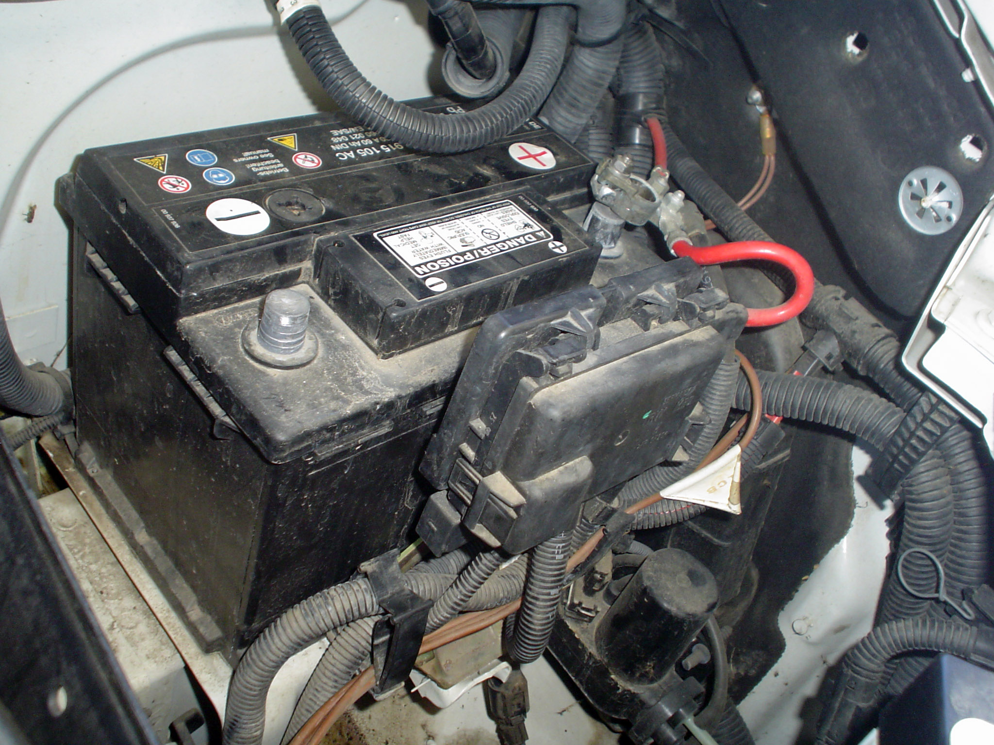
VW Fuse Box (Engine):
There is one main fuse located on the driver's side just above
the battery. It is a 50 amp fuse and controls the radiator fan. The remaining
EuroVan fuses such as those normally found under the driver's seat are non-existent
on the Rialta.
Here are some photos showing the engine fuse block
that is mounted just in above the battery hold down clamp. These photos are in
high resolution and provide good detail of the area.
 This photo shows the battery area with the closed fuse box just in front of it.
 This photo is a close up of the connections inside the fuse box.
NOTE - The following message posted to the Yahoo
Group Rialta-Tech indicates the importance of checking the connection within this
fuse box.
While preparing for a trip, I noted that the
house batteries did not indicate a full charge when the engine was running.
I checked the voltage at the batteries, checked at 11 volts. My first thought
was that the isolation solenoid located in coach battery compartment had failed,
but after checking voltage from the engine alternator it also was reading too
low, approximately 11 volts. I must mention that the charge indicator
in the instrument panel would go out when engine was running. I checked voltage
at the battery for the engine and as expected it also was too low, approximately
11 volts. With all my checks I felt sure that the alternator was not charging.
I drove to work and checked charging system on a modern tester and yes the alternator
test results showed no output. So looked like I was going to purchase a new
alternator.
The trip I was preparing for was for my son
and family with some friend attending the University of Kentucky and Louisville
Cardinal yearly football game. I called him with the bad news that they could
not use the Rialta. After taking a nap, I when back to the Rialta, removed the
front grille and loosen the front panel so I could see the alternator. I used
a test light at the alternator output wire and the light should have indicated
battery, but did not. I located attached to the front of battery what is a plastic
panel that contains wire connection and fuse metal strips. All of the strips
checked OK. When you look at this plastic panel the connection on the right
is a fuse strip with 175 amp. The reason the alternator was not charging was
caused by the lower bolt that holds the wire leading from the alternator was
loose. I tighten the bolt and the charging system problem was solved. At that
time, my voltage reading was 12.9 to 13 volts. Also checked house batteries
with engine running and they also indicated that the alternator was doing it
job. At this point I called my son to let him know they would be able to use
the Rialta to attend the game.
I rechecked what I had found and noted that
the bolt was loose again, after further checking what was happening was that
the plastic that hold the bolt was melting because of the heat created by loose
connection, it was apparent that this failure had been going on for a long period
of time. This plastic fuse panel has and extra circuit not being used so I disassemble
panel and relocated the alternator circuit to that position. What I need to
do will be to purchase a new panel, but for now this solves a problem that has
going on for a period of time. I feel there has to other Rialta with the same
problem, hopes this information will save someone from purchasing a new alternator
and grief
Don Riley 2000QD
Mon, 05 Sep 2005
[ return to top ]
Fuse Panel Connections
The following information covers electrical connections and
plugs to the rear of the fuse/relay panel. It completes and supplements the information
in the appropriate Service or Repair Manual for the fuse/relay panel section and
should be used in conjunction with the wiring diagram for the vehicle or system
in question. Volkswagen part numbers shown here may or may not match those on
your panel, however, if you panel visually matches the diagram, it is correct
for your application.
Fuse/Relay Panel - Rear Connections
(Volkswagen Part Number 357 937 039)
| A1 |
Yellow |
8 pin |
Headlight wiring harness |
| A2 |
Yellow |
8 pin |
Headlight wiring harness |
| B |
Green |
6 pin |
Headlight washer wiring harness |
| C |
Yellow |
8 pin |
Headlight or wiper motor wiring harness |
| D |
Green |
12 pin |
Miscellaneous equipment, varies (A/C, A/T, heated seats, seat belt warning,
etc.) |
| E |
Green |
5 pin |
Instrument or brake light wiring harness |
| F |
White |
10 pin |
Engine compartment/engine management, wiring harness, right side (position
10 open) |
| G1 |
White |
12 pin |
Engine compartment/engine management, right side |
| G2 |
White |
12 pin |
Engine compartment/engine management, right side (position 12 open)
|
| H1 |
Red |
10 pin |
Steering column switch wiring harness |
| H2 |
Red |
8 pin |
Steering column switch wiring harness (position 8 open) |
| J |
Red |
10 pin |
Steering column switch wiring harness |
| K |
Black |
12 pin |
Rear wiring harness |
| L |
Black |
8 pin |
Rear/Parking brake wiring harness (position 8 open) |
| M |
Black |
6 pin |
Rear/fuel tank wiring harness |
| N |
Green |
6 pin |
Air conditioning wiring harness |
| P |
Blue |
10 pin |
Rear window defroster/fog light wiring harness |
| Q |
Blue |
6 pin |
Fresh air blower fan wiring harness (position 10 open) |
| R |
Blue |
10 pin |
Light switch wiring harness |
| S |
White |
5 pin |
Engine compartment/wiper motor wiring harness, right side |
| T |
Green |
2 pin |
Individual circuits |
| U1 |
Blue |
14 pin |
Instrument cluster wiring harness |
| U2 |
Blue |
14 pin |
Instrument cluster wiring harness |
| V |
Green |
4 pin |
Steering column switch Multi-function indicator wiring harness |
| W |
Green |
6 pin |
Miscellaneous optional equipment, varies with vehicle type |
| X |
Green |
8 pin |
Warning lamp wiring harness |
| Y |
n/a |
1 pin |
4 single point connectors for terminal 30 circuit (some may be bridged
with red connector) |
| Z1 |
n/a |
1 pin |
Single point connector |
| Z2 |
n/a |
1 pin |
Single point connector for terminal 31 circuit |
| 30 |
n/a |
1 pin |
Single point connector for terminal 30 circuit (may be bridged to 30B
with red connector) |
| 30B |
n/a |
1 pin |
Single point connector for terminal 30 circuit (may be bridged to 30 with
red connector) |
Note: Terminal and harness assignments
for individual connectors will vary depending on vehicle equipment level, model,
and market. Always consult appropriate wiring diagram for specific terminal assignments.
[ return to top ]
|